Threaded Insert Clearance Hole Design Guidelines
Use these design guidelines to assist you with designing clearance holes for threaded inserts for plastic applications.
Designing Clearance Holes for Threaded Inserts?
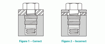
When designing a mating component clearance hole, it is very important that the threaded insert, not the plastic, carries the load. The hole in the mating component should be larger than the outside thread diameter of the screw and smaller than the insert diameter. This prevents the insert from jacking out (Figure 1). When the mating component hole is larger than the insert diameter, a jack-out condition exists (Figure 2).

Design Considerations
Hole sizes are not core pin sizes.
Core pins should be designed to allow for the shrinking of plastic.
For solid (blind) inserts and threaded studs, we recommend adding a small vent at the bottom of the hole to allow trapped air and other gasses to escape.
Expect your inserts to seat flush with or .005″ above the plastic surface.
Boss Diameter / Wall Thickness
The performance value of an insert is proportional to the wall thickness (boss diameter) surrounding it. When an increase in wall thickness does not produce an increase in performance, optimum thickness has been reached. Optimum thickness, on average, is two times the hole diameter. If a boss is too large, a sharp drop in performance may result because the hole may become oversized as the molded plastic shrinks. When the hole diameter is larger than recommended, less material is displaced and the insert does not become fully encapsulated in the plastic part – resulting in lower performance values.

Hole Specifications
Hole depth is the key to achieving a flush installation and preventing excess plastic from forming on the threads at the bottom of the insert. Countersinks should not be molded into a hole where an insert is to be installed.
All of our inserts have a pilot or “lead-in” diameter that assures proper alignment of the insert during installation, as well as a counterbore or countersink at each end of the insert for easy installation of the mating screw.
Should alterations in hole sizes be necessary, please contact our Engineering Department for technical assistance.
Remember, there are two types of molded holes referred to in this catalog. The “straight hole” has a maximum of a 1° taper or 1/2° per side. The “tapered hole” has an approximate 8° included angle.

Have Questions?
If you didn't find the answer you were looking for, consider talking to one of MW experts.