Swage Standoffs Installation Guide
Follow these instructions for a superior installation of both plain swage standoffs and knurled swage standoffs. Knurled swage standoffs offer more holding power than plain standoffs, and eliminate electrical connection breaks due to loosening and spinning of the standoff because of high torque stresses.
HOLE SPECIFICATIONS
The Swaging Process
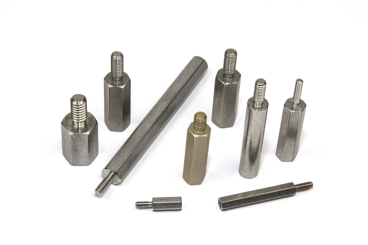
Plain Swage Standoff – A plain swage standoff (no knurl) requires a STRAIGHT HOLE. The hole diameter in the board or panel is the same as the shank (or shoulder) diameter of the standoff with a tolerance of +.003″/-.000″ (+.076 mm/-.000 mm).
Partial Knurl or Full Knurl Swage Standoff – A partial knurl or full knurl swage standoff requires a STRAIGHT HOLE in a printed circuit board. The hole diameter in the board is .010″ to .012″ smaller than the shank (or shoulder) diameter of the standoff with a tolerance of +.005″/-.000″ (+.13 mm/-.000 mm).
Methods of Installation

Swage
While some dimensions of the punch and anvil change with the size of the swage standoffs, the following dimensions remain constant:
- The punch is 2.5″ in overall length and .5″ OD
- The anvil is 1″ in overall length and .5″ OD with a 1/2-24 external thread
- Punch and anvil part numbers for swaging are listed on the individual pages of plain and partial knurl swage standoffs
Have Questions?
Talk with our experts today and let us help you figure out the best solution.