How to Select a Torsion Spring
MW Components' Century Spring location offers a selection of stock torsion springs with legs of equal length oriented at varying unloaded angles. We also produce custom springs made to your exact specifications. To order, shop our selection of stock torsion springs or request a quote for custom springs.
How to Select a Torsion Spring
MW Components offers a selection of stock torsion springs with legs of equal length oriented at varying unloaded angles. We also produce custom torsion springs made to your exact specifications. Learn more about our torsion springs.
What is a Torsion Spring?
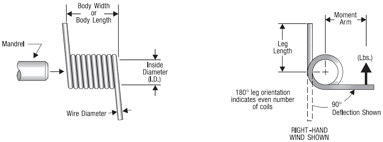
The torsion spring configuration is created for the purpose of storing and releasing angular energy or for the purpose of statically holding a mechanism in place by deflecting the legs about the body's centerline axis. A spring of this type will reduce in body diameter and increase slightly in body length when deflected in the preferred direction of the fabricated wind. The direction of the fabricated wind can be important for torsion spring applications due to the leg bearing/attachment locations having to be on the left or right side upon assembly. A torsion spring is normally supported by a rod (mandrel) that is coincident with the theoretical hinge line of the final product.
Torsion Spring Design Information
Torque and Deflection
To begin, determine the torque the spring will be expected to develop. The torque (or moment) is simply the applied force (pounds) pushing perpendicularly on a leg or leg extension times its distance (inches) to the centerline of the spring body. Then, determine the angular deflection (degrees of motion) through which the spring leg is required to rotate. Divide the torque by this angle to obtain the spring constant (rate) you require. (Rate = Torque / Degrees) Or, if the torque required to rotate the spring through a given angle is required, use the formula (Torque = Rate x Degrees).
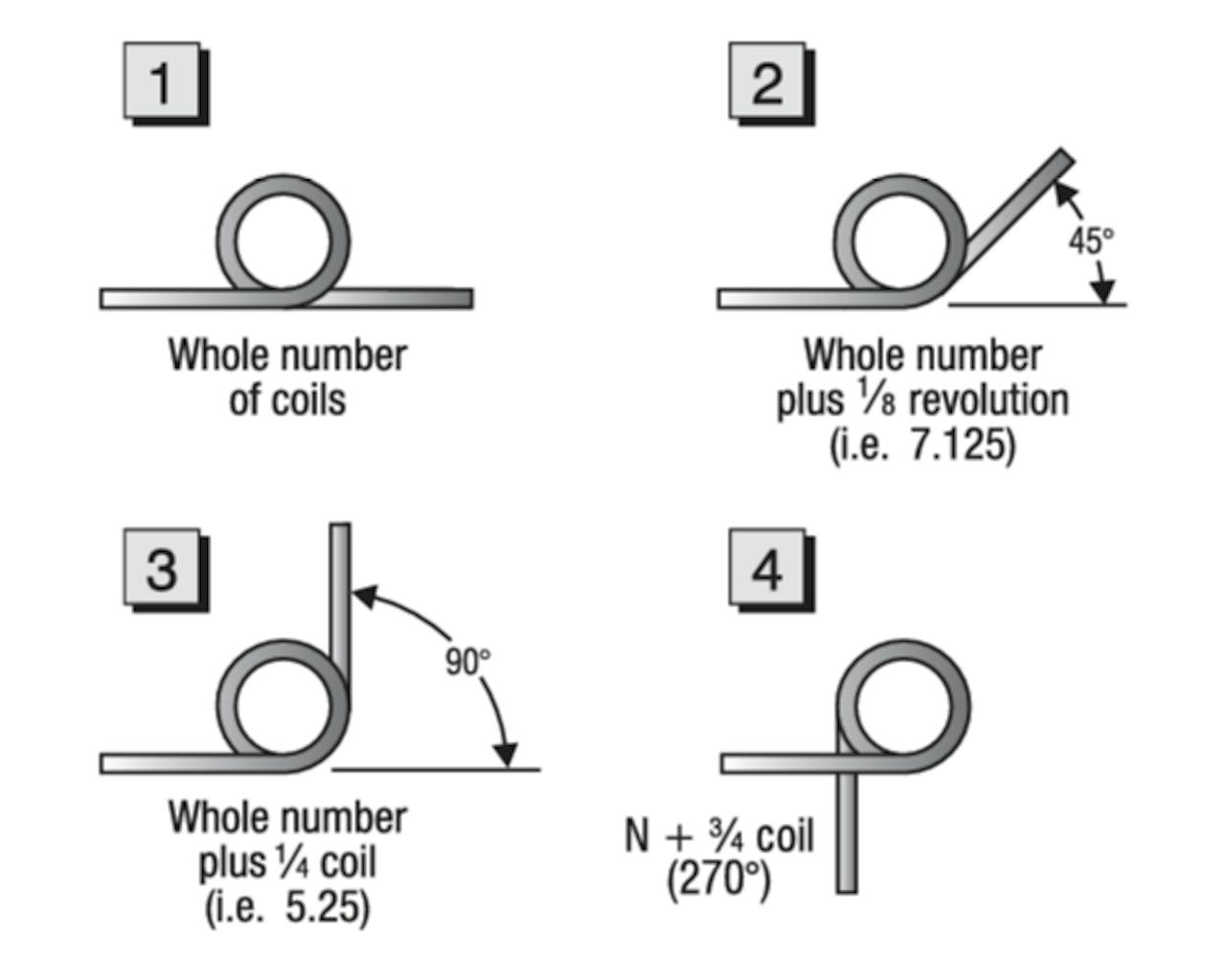
From our online store, search for an acceptable rate. When found, observe the spring’s “Inside diameter” (I.D.) and “Body Width” (length) for size compatibility with your application. The “Suggested Maximum Deflection” reflects limits (degrees) that should produce a long service life with average cycling. These values can be increased by as much as 20% for static (non-oscillatory) applications. Near-infinite service life can be possible using values of about 35% of those listed. The initial unloaded relative-leg-angle orientation is determined by the number of coils in the spring body. Use the diagram to the right to better understand relative-leg-angle orientation. In reference to spring wind, if it takes the right hand and index finger to simulate the spring’s end view, then it would be a right-hand wound spring.
The body (solid) lengthening due to deflection increases approximately by one wire diameter for each complete leg revolution (360 degrees). The body inside diameter (I.D.) decreases according to: I.D. = N N + REVs x I.D. (unloaded) (Where: N = Number of coils, REVs = Number of leg revolutions). Once the inside diameter of the load-contracted spring body is determined, the supporting mandrel’s maximum diameter is usually set to about 90% of this value.Note: If the spring needed for your application cannot be found in our inventory, we can fabricate it for you. Simply request a quote.
Finding Spring Rate and Spring Stress Rate
The basic spring rate and wire stress for a torsion spring can be estimated with the formulas shown below.
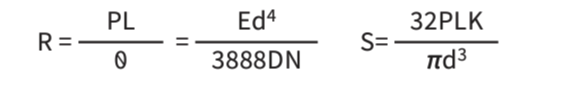
Note: Bending deflections of long legs under load must be considered for some applications and added to the total angular deflection.
Where:
- P = Load, lbs.
- L = Moment arm, inches
- θ = Angle of deflection, degrees
- E = 30x106,(28x106/stainless) Young’s Modulus
- d = Wire diameter, inches
- D = Body mean diameter (O.D. - d), inches
- O.D. = Outside diameter, inches
- N = Number of coils
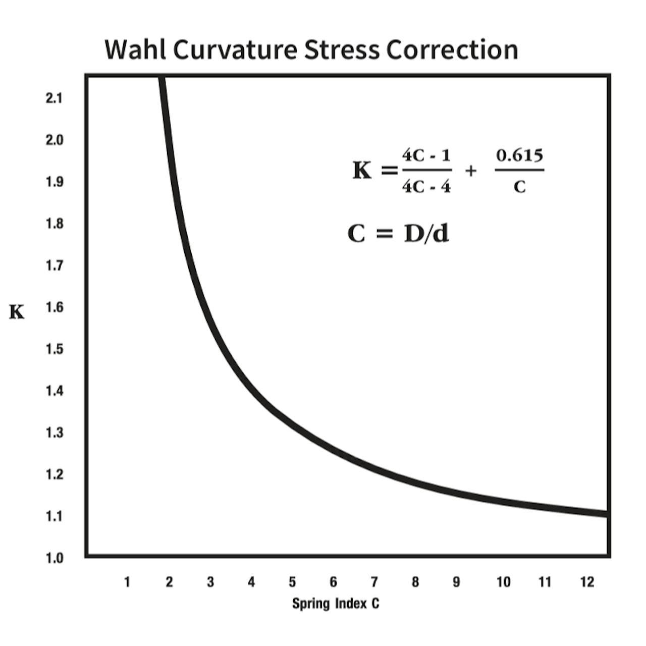
- K = Stress correction factor (see plot below)
- R = Rate (constant), in.-lbs./deg.
- S = Stress (in bending), p.s.i.
Minimum Tensile Strength
Minimum Tensile Strength (MTS) values vary with the spring-wire diameter. Further, 30 to 45 percent of the MTS value, depending on the material type, is used as a corrected stress target to produce a long fatigue life. For more information on MTS values by material type, ask an expert. For custom spring designs, request a quote.
Spring Characteristics
Materials
Century Spring uses the highest grades of spring wire to fabricate our torsion springs. To create cost-effective warehousing of our stock spring inventory for our customers, we offer material certifications for custom springs only. Stock torsion springs are offered in Stainless Steel 302. For stock springs, we offer an optional material verification statement for a $25 fee. Certifications of conformance for geometric tolerances set by the Spring Manufacturers Institute (SMI) are available for our stock springs on request.
Note: “Spring Steel” is a broad term for music wire, hard-drawn wire, and oil-tempered wire.
Finishes
The finishes available for our torsion springs include:
- Zinc
- Gold Irridite®
- Black Oxide
- Passivated (upon request)
- None (can be plated upon request)
Tolerances
Tolerance values for torsion springs depend on the body-diameter to wire-diameter ratio and are about +/- 10% in torque and +/- 5% in diameter.
Contact Us
For further design and engineering resources, visit the MW Components resource center or for specific questions related to our products or services, contact us.