How to Select a Compression Spring
MW Components' Century Spring location stocks the most extensive inventory of high-grade, cylindrically-shaped compression springs in the world. We also produce custom compression springs for unique applications. Compression springs discussed in this section are produced using round wire, though rectangular wire can also be used to reduce the solid height or increase space efficiency.
Ready to get started? Try our compression spring calculator.
An Introduction to Selecting Compression Springs
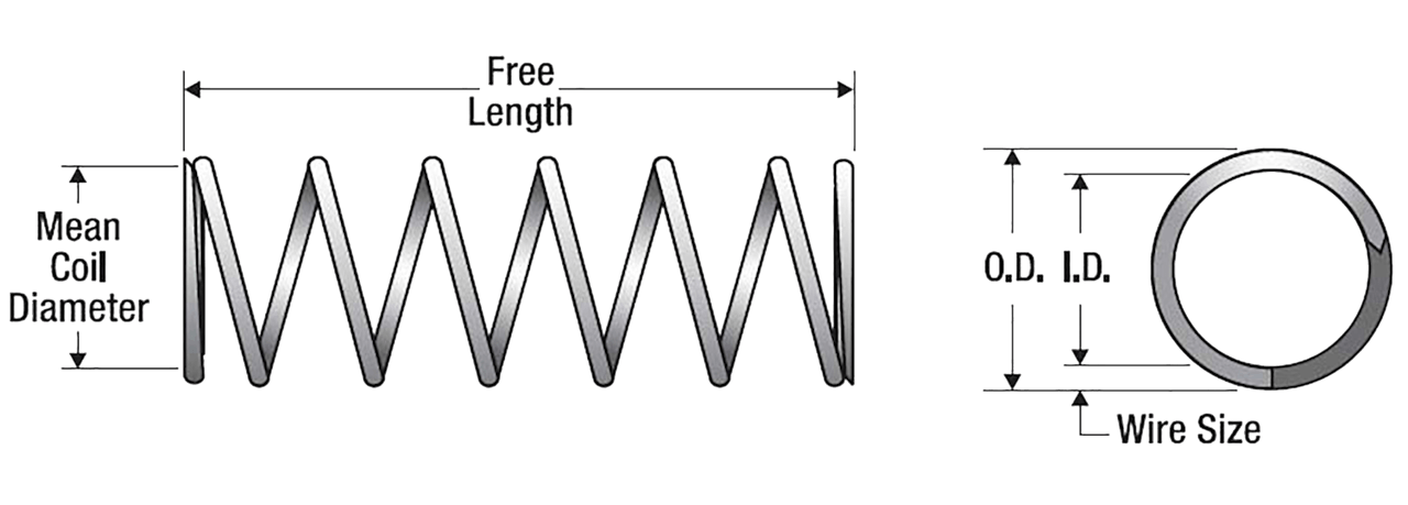
Begin by finding the outside diameter (O.D.) and length or rate (strength) you require. You can reference the diagram shown on the right.
Spring rate is the load (pounds) it takes to deflect (compress) the spring one theoretical inch, i.e., if the rate = 40 lbs./1 in., it would take 10 pounds to deflect it 1/4 inch, or 80 pounds for 2 inches, etc.
• If the length or rate is not known, but the installed working length (WL) is, then select a spring — say 30% longer — than the WL. You must know the load at the WL. Just subtract the WL from the spring’s selected free length and multiply by its rate to obtain the load to compare with your required value.
• If the load required is not obtained, select a new candidate with either an increase or decrease in rate (strength) or free length.
• Be certain that the tabulated solid length (completely compressed) for your candidate spring indicates enough room for deflection and also that the deflection is not significantly greater than the tabulated “Maximum Suggested” for stress reasons.
Note: If the spring needed for your application cannot be found in our inventory, we can fabricate it for you. Simply request a quote.
Design Information
Finding Compression Rate
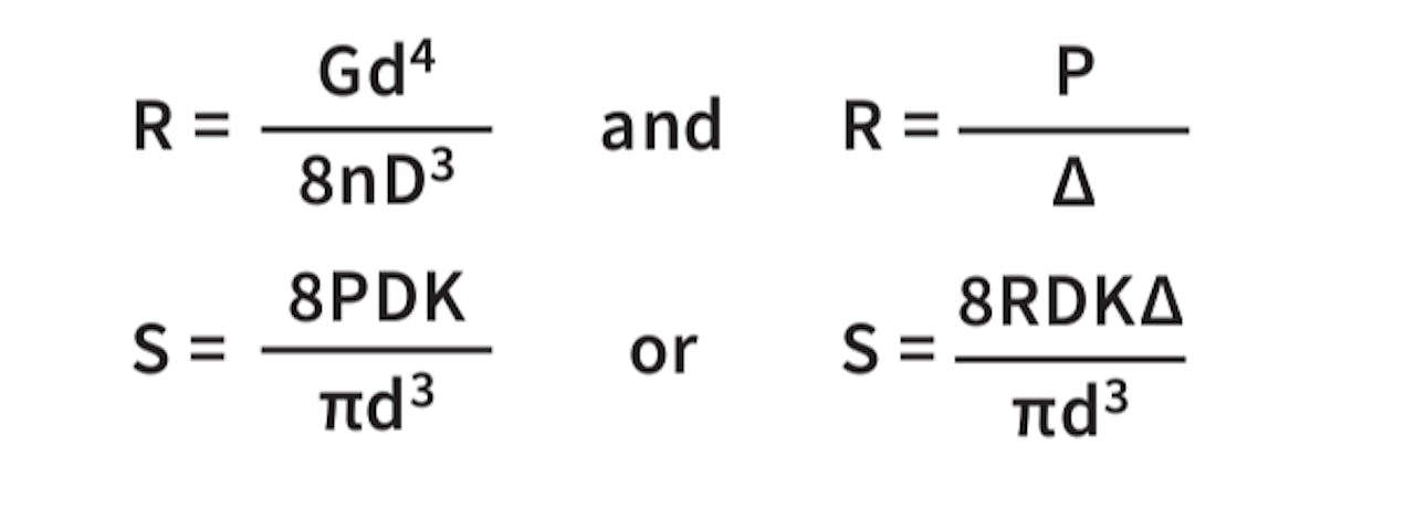
The basic compression rate and wire stress for a compression spring can be estimated with the formulas shown on the right.
Note: One should not employ the curvature (k) correction stress in an expression solving for deflection. Use the uncorrected stress only, or errors will occur. The uncorrected stress can be used for static applications.
Where:
D = Mean diameter, (O.D. - d) inches
d = Wire diameter, inches
G = Modulus (spring steel = 11.5x10⁶, stainless = 10x106), p.s.i.
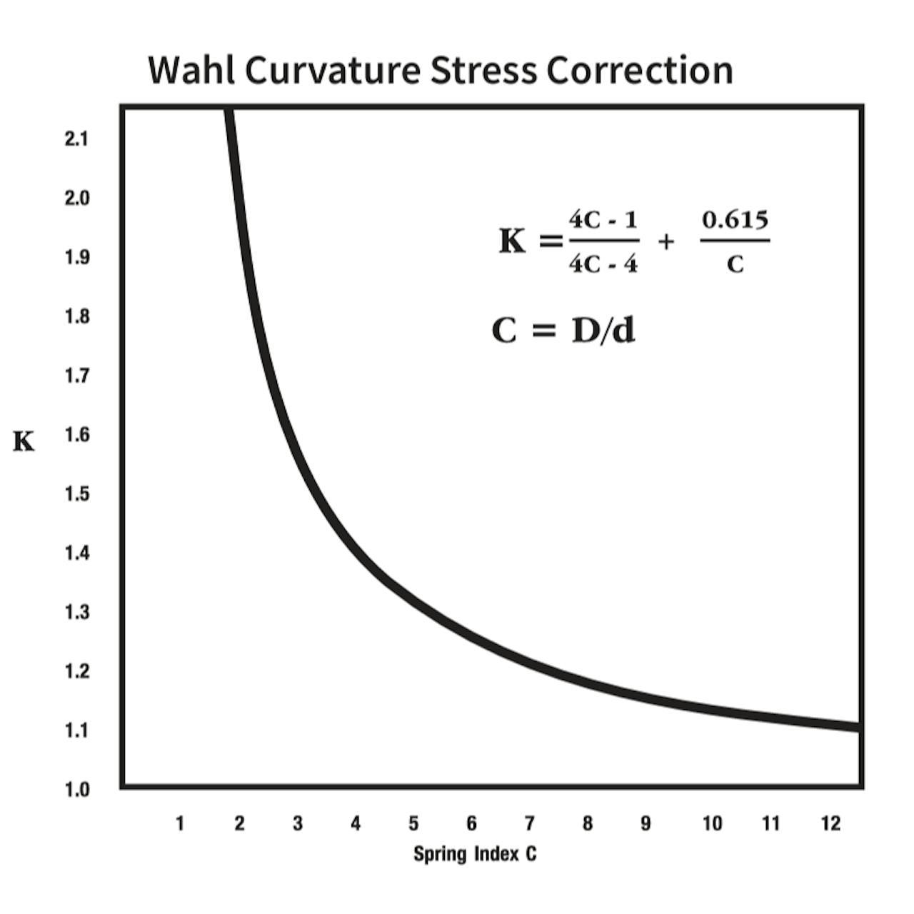
K = Stress correction factor (see plot below)
N = Number of total coils
n = Number of active coils
P = Applied load, pounds
p = Pitch, distance between centerlines of wires of adjoining coils
R = Spring rate, pounds per inch (lbs./in.)
S = Wire stress, psi
Δ = Deflection, inches
π = 3.14
Spring Stress Rate
Minimum Tensile Strength (MTS) values vary with the spring-wire diameter. Further, 30 to 45 percent of the MTS value, depending on the material type, is used as a corrected stress target to produce a long fatigue life. For more information on MTS values by material type, ask an expert. For custom spring designs, request a quote.
Type of Spring Ends
| Spring Characteristics | Open | Open & Ground | Closed | Closed & Ground |
|---|---|---|---|---|
| Solid Length | d (N + 1) | d x N | d (N + 1) | d x N |
| Active Coils | N | N - 1 | N - 2 | N - 2 |
| Total Coils (N) | n | n + 1 | n + 2 | n + 2 |
| Free Length (L) | (p x N) + d | p x N | (p x n) + 3d | (p x n) + 2d |
Spring Characteristics
Service Life
It should be noted that if critical force-versus-deflection linearity is required, only the center 20 to 80 percent of the available deflection range should be employed. Thus, reserve at least the first and last 15 to 20 percent of the range for potential spring-end and adjacent coil-contact effects. These effects can be largely ignored for the majority of spring applications. The column “Suggested Maximum Deflection” found in the following pages of inventory reflects the recommended inches of travel to obtain a statistical service-life of approximately 100,000 cycles (deflections) with infrequent breakage. This can be realized if the spring in question is not subjected to shock loads, rapid cycling, temperature extremes, corrosion or stress values above those previously recommended. If the spring is statically loaded (not cycling), a near-infinite life can be expected.
Materials
The highest grades of spring wire are used for fabricating our springs. To create cost-effective warehousing of our stock spring inventory for our customers, we offer material certification for custom springs only. For stock springs, we offer an optional material verification statement for a $25 fee. Certifications of conformance for geometric tolerances set by the Spring Manufacturers Institute (SMI) are available for our stock springs upon request.
“Spring Steel” is a stock inventory term covering: Music wire, Hard-drawn (MB) wire, and Oil-tempered wire.
Additionally, stock compression-spring materials include: Stainless Steel 302 and 316, Beryllium Copper, and Phosphor Bronze.
Tolerances
Our Century Spring location manufactures stock springs to commercial tolerances defined by the SMI. Calculated rates and loads based on the SMI geometric tolerances have an approximate +/- ten percent. Low or high-index springs will have higher values. Compression springs characteristically have an hourglass shape when coiled on an automatic coiler; therefore, outside/inside tolerancing is applied to end coils only. This is an important consideration when selecting a spring that fits over a rod or inside a cylinder. Contact us for a custom quote, if tighter tolerance values are required. Regarding angle tolerance, the plane of the ground end of a spring is usually within five degrees of the perpendicular-to- the-body axis of the spring. Please note, springs with a coil count less than 4 are made to physical dimensions only. The rate is not certified because of the low amount of active coils. The listed solid height dimension is for reference only.
Ends
The compression spring ends configuration is indicated in the “Ends” column of our inventory listings which are: Closed (C) - The last coil at each end is bent back to touch the previous coil to create a flat base. Closed and Ground (C&G) - The closed ends of a spring ground to a more accurate flat base. This will also reduce the solid length. Open (O) - The spring end coils remain open, maintaining the spring machine’s helical wind shape.
Direction of Helix (Wind)
The wind direction of our stock springs varies, both RHW and LHW. Stock springs are not sorted for wind direction. To order springs wound to a specific direction, please contact us for a custom quote.
Finish
The finishes available for our compression springs include:
• Zinc
• Gold Irridite®
• Black Oxide
• Passivated (upon request)
• None (can be plated upon request)
Contact Us
For further design and engineering resources, visit the MW Components resource center or for specific questions related to our products or services, contact us.