ASM Socket Cap Screw Data
MW Components' ASM location offers a wide variety of socket cap screws. Learn more in the data below, or shop socket cap head machine screws.
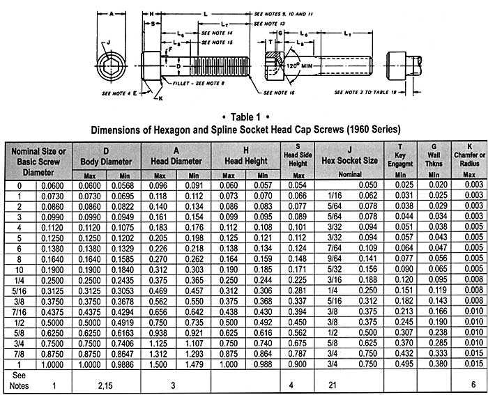
1. Nominal Size. Where specifying the nominal size in decimals, zeros preceding decimal and in the fourth decimal place shall be omitted.
2. Body. The term body refers to the unthreaded cylindrical portion of the shank for those screws not threaded to the head.
3. Head Diameter. Heads may be plain or knurled at the option of the manufacturer unless otherwise specified by the customer. For knurled screws, the maximum head diameter shall be measured across the tops of the knurl and the minimum head diameter shall be the diameter of the un-knurled portion, or the diameter across the tops of the knurl for those screws not having an un-knurled portion, just above the radius or chamfer at the bottom edge of the head.
4. Head Chamfer. The head shall be chamfered. The chamfer E shall be at an angle of 30 – 45 degrees with the plane of the top of the head. The edge between the top of the head and the chamfer may be slightly rounded.
5. Bearing Surface. The plane of the bearing surface shall be perpendicular to the axis of the screw within a maximum deviation of 1 degree.
6. Edge of Head. The edge between the bearing surface and the side of the head may be broken (rounded or chamfered) but the radius or chamfer measured along the bearing surface shall not exceed the values listed for K.
7. Concentricity.
a. The head shall be concentric with the shank within 1 percent of the basic screw diameter, D maximum, 2 % total runout) or 0.006-inch total runout, whichever is greater, when held within one diameter of the head but beyond the fillet.
b. The socket shall be concentric with the shank within 1-1/2% of the basic screw diameter, D maximum. (3% total runout) or 0.005 in. whichever is grated for sizes through 1/2 in and 3% (6 % total runout) for sizes above 1/2 in.
c. Total runout between thread, body, and head: Screws shall assemble into a compound hole which is threaded at one end to the basic thread size (3B minimum), for a length equivalent to 1-1/2 D, counterbored at the other end to diameter Ae listed in Table 1C, and whose center portion is equal to De. Diameters De and Ae shall be concentric with the axis of the thread. The length of the center portion shall be equal to the screw length minus two screw diameters (2D). The starting thread shall be chamfered and the junction between diameters Ae and De shall be rounded to a value equal to F maximum.
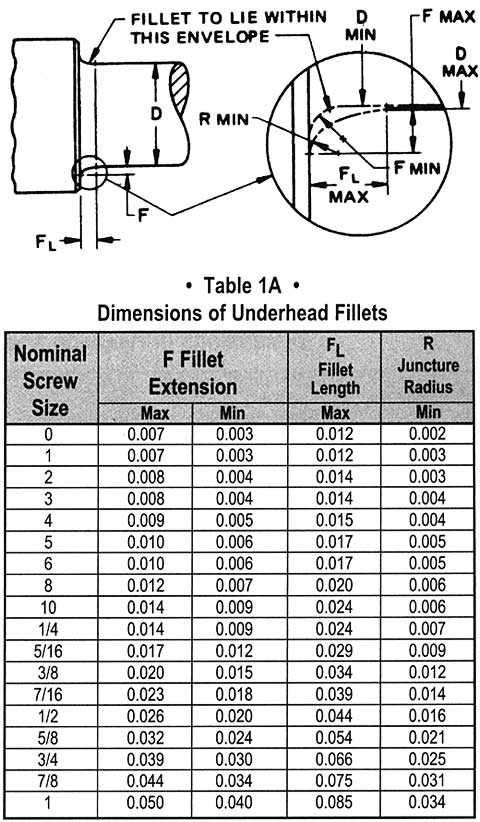
8. Fillet. For all lengths of screws, the form of the underhead fillet shall be optional, as depicted in Figure 1, provided it is a smooth and continuous concave curve fairing into the bearing surface of the head and the screw shank within the envelope established by the limits for fillet extension, length and juncture radius specified in Table 1A.
9. Length. The length of the screw shall be measured parallel to the axis of the screw from the plane of the bearing surface under the head to the plane of the flat of the point. The portion of the screw contained within dimension L is commonly called the shank. The basic length dimension on the product shall be the nominal length expressed as a two-place decimal.
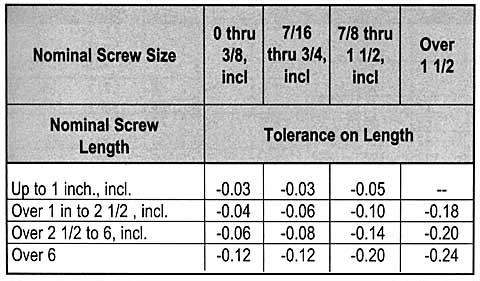
10. Length Tolerances. The allowable tolerance on length shall be as tabulated below:
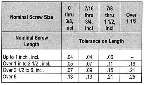
11. Length Tolerances. The allowable tolerance for LEAD POINT captive screws only shall be as tabulated below.
12. Threads. Threads shall be Unified external threads with radius root: Class 3A UNC and UNF Series for screw size 0 (0.060 in.) through 1 in.: Class 2A UNC and UNF Series for sizes over 1 in. to 1-1/2 in., inclusive: and Class 2A UNC Series for sizes larger than 1-1/2 in. Class 3A does not provide a plating allowance. When plated products are required it is recommended that they are procured from the manufacturer. (See paragraph 1.8).
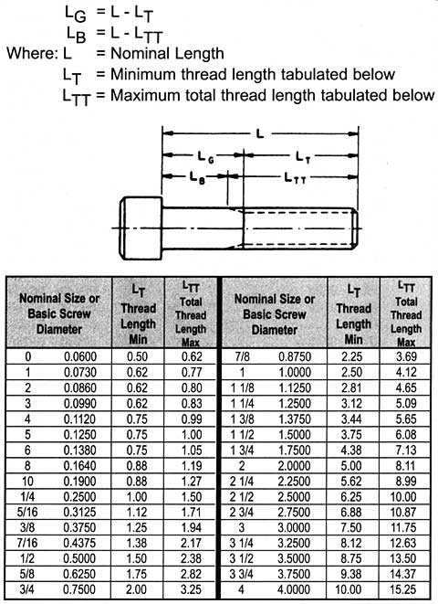
13. Thread Length, LT. The length of the thread shall be measured, parallel to the axis of the screw, from the extreme point to the last complete (full form) thread. The thread length on socket head cap screws shall be as defined by Table 1B and notes thereto.
14. Griping Gaging Length, LG. The grip gaging length is the distance, measured parallel to the axis of the screw, from the bearing surface of the head to the first complete (full form) thread under the head (see Table 1B).
15. Body Length, LB. The body length is the length, measured parallel to the axis of the screw, of the unthreaded portion of the shank (See table 1B).
16. Screw Point Chamfer. The point shall be flat or slightly concave and chamfered. The plane of the point shall be approximately normal to the axis of the screw. The chamfer shall extend slightly below the root of the thread and the edge between the flat and chamfer may be slightly rounded. The included angle of the point should be approximately 90 degrees. Chamfering of screw sizes up to and including size 8 (0.164 in.) shall be optional.
17. Material. Steel, corrosion-resistant. Cap screws shall be fabricated from austenitic corrosion-resistant steel of types 18-8, AISI 384, or equivalent types, and shall have a minimum tensile strength of 80,000 psi for sizes up to and including 5/8 in and 70,000 psi for sizes larger than 5/8 in.
18. Surface Roughness. For alloy steel screws of up to and including 5/8 in., and nominal lengths equal to or less than 8 times the basic screw diameter, the surface roughness of the screws before plating shall not exceed 63 microinches (arithmetical average) on the fillet and head bearing surfaces, nor exceed 32 microinches (arithmetical average) on the threads.
For larger sizes, longer lengths, and corrosion-resistant steel screws, the surface roughness of the screws prior to plating shall not exceed 125 micro-inches (arithmetical average) on the body (see Note 2), fillet (see Note 8), and head bearing surfaces.
Normally, it shall be sufficient to ascertain that these surfaces on screws have the equivalent of a smooth machined finish by visual comparison with know surface standards. However, where it is practical and deemed necessary to measure these surfaces with commercially available equipment, roughness measurements shall be taken axially on the body and fillet surfaces, and circumferentially on the bearing surface.
19. Drawings. On socket screw drawings when the distance from the bearing surface of the head to the threading is dimensioned, regardless of the type of thread representation, the dimension should be noted to indicate whether Body Length or Grip Length is required.
20. See Table 7 for spline socket dimensions and Appendix 1 for gaging of spline sockets.
21. See Table 6 for hexagon socket dimensions and Appendix 1 for gaging of hexagon sockets.
22. Designation. Hexagon and Spline Socket Head Cap Screws shall be designated by the following data in the sequence shown: Nominal size (number, fractional or decimal equivalent); threads per inch; length (fractional or decimal equivalent); product name; material; and protective coating if required. See examples below: 6-32 x 3/4 Hexagon Socket Head Cap Screw, Alloy Steel .138 – 32 x .75 Spline Socket Head Cap Screws, Alloy Steel, Cadmium Plated.
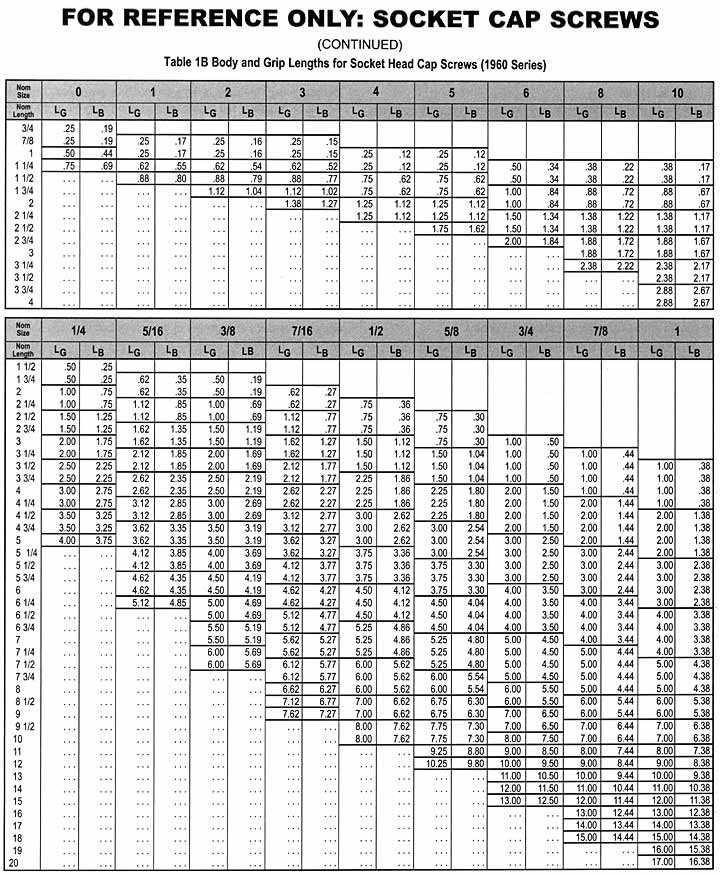
1. The tabulate LG values are maximum and represent the minimum design grip length of the screw. They shall be measured from the bearing surface of the head to the face of a GO thread ring gage, having the thread countersink and /or counterbore removed, which has been assembled by hand as far as the thread will permit. The tabulated LB values are minimum and represent the minimum body length of the screw. They are equal to LG minus 5 times the pitch of the UNRC thread for the respective screw size.
2. Screws having nominal lengths falling between those for which LG and LB values are tabulated in Table 1B shall have Lg and LG dimensions conforming with those of the next shorter tabulated nominal length for the respective screw size. For example: for a 1/4 in. size screw, 1 7/8 inch long, LG=0.50 inch and LB =0.25 inch.
3. For screws of nominal length above the heavy line in Table 1B the complete (full form) threads measured with a thread ring gage, having the thread chamfer and/or counterbore removed, shall extend to within two pitches (threads) of the head for sizes 0 (0.060 in.) through 5/8 inches inclusive; and shall extend as close to the head as is practical for sizes larger than 5/8 inches.
Screws over 1 inch in diameter and of lengths shorter than the minimum thread length LT plus 5 times the pitch of the UNRC thread for the respective screw size shall have complete (full form) threads extending as close to the head as is practicable. See Note 4 for LT values.
4. For screws of nominal lengths longer than those for which LG and LB values are tabulated in Table 1B and for screws over 1 inch in diameter, the maximum grip gaging length LG and the minimum body length LB of the screws shall be determined as follows:
All drawings and designs herein have been reviewed and have been determined to meet the required specifications contained herein.
Looking for screws? Browse all our available screws.
Ask An Expert
Can't find the information you need? Ask an MW Expert.