Technical Guide to Coil Spring Manufacturing
Tolerances Stress Correction Formulas Surface Protection Buckling Natural Frequency
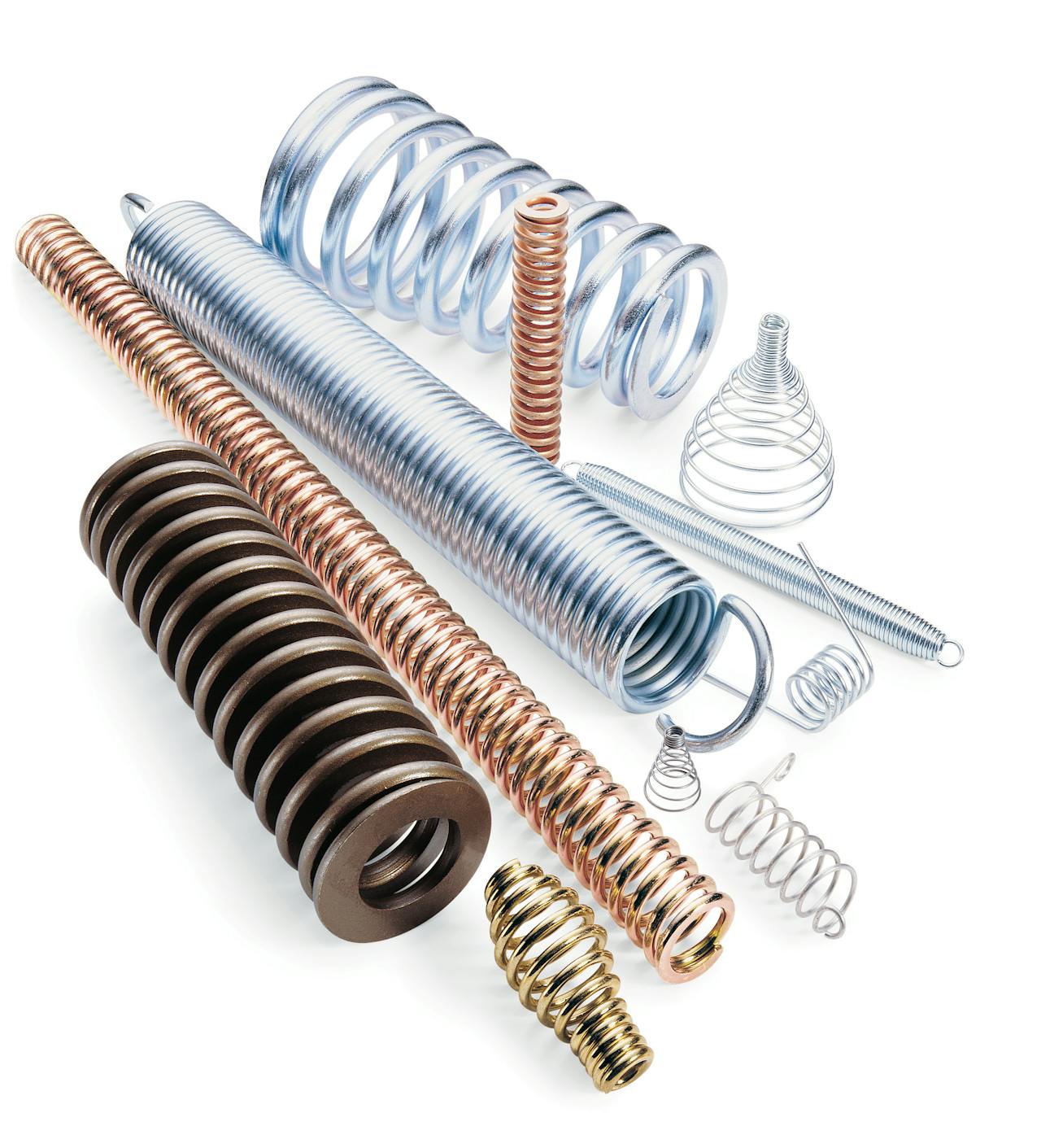
Coil Spring Manufacturing Process
Whether you have an existing spring application in need of re-engineering or a new one that requires designing this guide will help. The engineering team and MW Components has been manufacturing springs for well over 100 years and has refined the coil spring manufacturing process for the industry – for all types of coil springs.
The scope of this manual is limited to data which will be helpful to the design engineer in solving problems frequently encountered in helical springs. General information such as maximum stress limits, relative costs of materials, and the more often used formulas are presented for references.
For the sophisticated engineer desiring more technical design information we highly recommend Dr. A.M. Wahl’s “Mechanical Springs” published by the McGraw-Hill Company.
Coil Spring Tolerances
Cold Wound Spring Manufacturing
The Spring Manufacturers Institute composed of over 300 major cold wound spring manufacturers has produced a handbook for “Standards and Design for Compression, Extension, Torsion, and Flat Springs.” This manual, available from your spring manufacturer, is highly recommended as a guide to practical tolerances and for its coverage of spring terminology, formulas and design information for cold-formed springs.
Hot Wound Spring Manufacturing
The accepted standard for manufacture and tolerances of how wound springs is ASTM-125, latest revision. This specification covers such points as tolerance on out side diameter, free height, maximum solid height, loaded height, and squareness, as well as definitions and inspection procedure.
The ASTM committee, composed of technical representatives of the major hot coil spring manufacturers, has cognizance over the updating of the specification to keep pace with technological advances.
Coil Spring Stress Correction
The conventional stress formulas for compression and extension springs shown in this guide give values in pure torsion. Most springs are used for light or moderate service where the life requirement will not exceed 10,000 cycles. It is generally accepted practice to ignore correction factors for such service.
For heavy duty service where life expectancy is 100,000 cycles or greater, total stress must be considered. The Wahl correction factor takes into account increased stresses caused by the curvature of the wire and shear. A corrected stress is obtained by multiplying the conventional stress by the appropriate Wahl factor.
In most elevated temperature tests where relaxation data are given for various temperatures and stresses, the stress figures include the Wahl correction factor.
Another stress correction factor, shown by H.C. Keysor, covers the increase in stress due to eccentric loading, being most pronounced in short springs. With only 2 active coils, this correction factor is 1.23, but with 4½ active coils, the factor drops to less than 1.10.
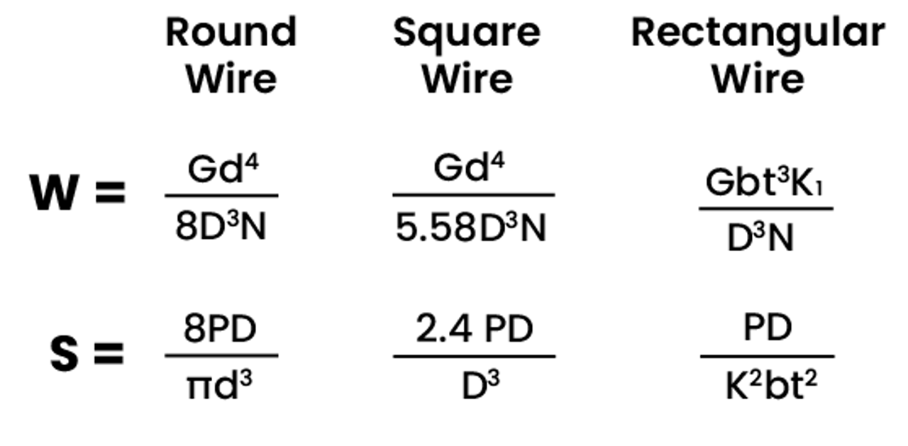
Compression & Extension Spring Formulas
Key
- W - compression rate (lbs/in)
- S - uncorrected torsional stress (PSI)
- G - torsional modulus
- d - wire diameter or square size (in)
- D - mean coil diameter (in)
- P - load (lbs)
- N - number of active turns
- b - long side of rectangular wire (in)
- t - short side of rectangular wire (in)
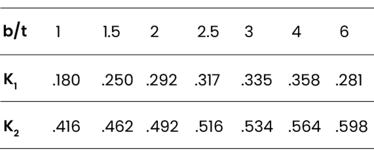
- K1 / K2 - constants (see table 2)
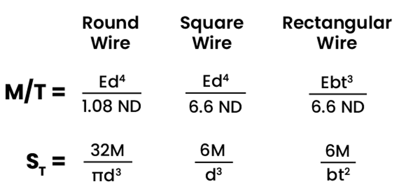
Torsion Spring Formulas
Key
- M - moment of torque (in-lbs)
- M/T - torque rate or moment of cause (in-lbs/360°)
- b - width or axial dimension
- S ₜ - tensional stress (PSI)
- E - modulus in tension (carbon or low alloy steel springs)
- 28,500 for hot wound
- 30,500,00 for cold wound
- t - thickness of radial dimension
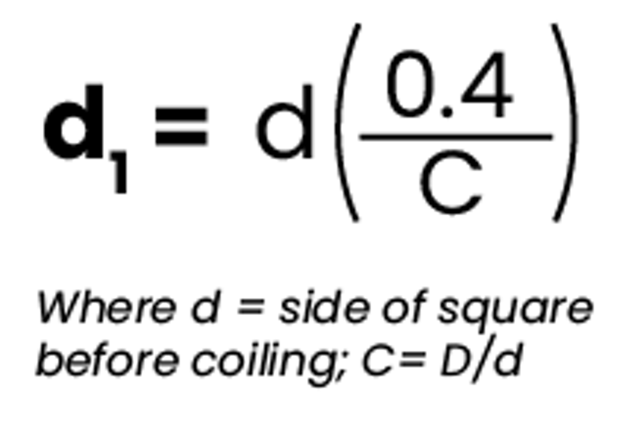
Square Wire Info
With square wire, coiling distortion creates a trapezoidal shape, increasing the size along the inside diameter, and hence the solid height. The increased side dl can be estimated:
- d - side of square before coiling
- C - D/d
Surface Protection
Rust and environmental pitting act as stress risers and may cause early failure in the best designed spring, carefully manufactured from otherwise sound material.
Where cost and other factors dictate against corrosion resistant materials, the spring surface, which is the most highly stressed area, must be protected. Unprotected shot peened steel springs start rusting almost immediately. Protection starts with choosing the right coating.
Powder Coating, often the coating of choice, offers impact, abrasion, salt spray, humidity, and chemical resistance that meets the majority of customer requirements.
Epoxy powder coatings are designed for general purpose interior use and for applications where maximum chemical and solvent resistance is required.
TGIC-Polyester powder coatings are substituted for those applications requiring PVC coating. They offer excellent exterior durability and good resistance to most chemicals and solvents except alkalis and ketones.
At DC Coil, we have our own in-house powder coating capabilities, making TCIC-Polyester coating our preferred choice. It offers a lower cost and quicker turnaround times than other coatings.
Electroplating cold wound springs made from oil tempered chrome vana dium or chrome silicon wire is not advisable. Electroless nickel plating is an effective substitute when cadmium is environmentally objectionable.
Dip painting to assure complete coverage with lacquer or enamel is another practical method, particularly for large springs. Water-based paints are now available for all colors in both lacquer and enamel.
Baking can be used for faster drying time and better adhesion when using water-based paints. This process usually involves individual handling. For this reason, springs small enough for barrel plating can be protected in this manner at a lower cost.
Oxide or phosphate coatings with supplemental oil or paint coatings are useful treatments, particularly for oil tempered chrome vanadium or chrome silicon wire springs. For limited protection against rusting on the shelf in inside storage, protective oils may be used.
The use of pre-coated wire, such as cadmium plated or galvanized wire, is practical for limited protection in small sizes for extension springs and compression springs with unground ends.
Hot dip galvanizing for finished springs is not normally practical. It has been successful only where large volume justifies the cost of very closely controlled processing.
Plastic coatings, such as polyvinyl chloride and nylon can be applied at a reasonable cost by the fluidized bed process for particularly corrosive applications.
Buckling
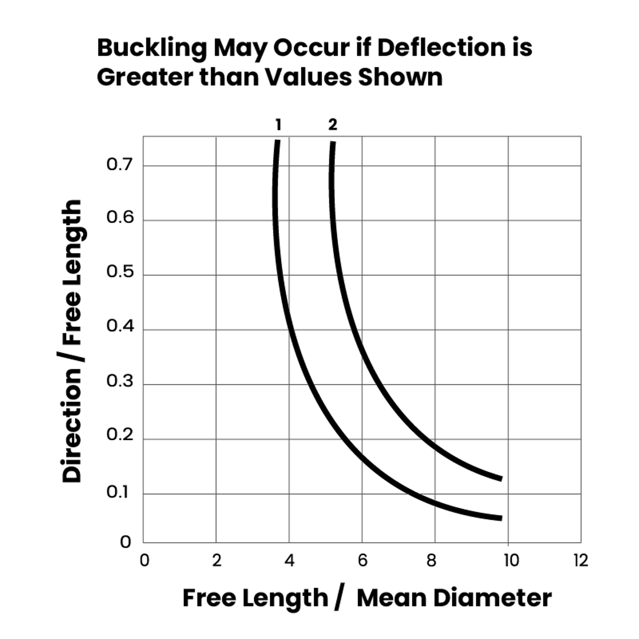
Where the free length of a compression spring exceeds four times the mean diameter, lateral deflection or buckling becomes notice able during compression.
Piloting and guiding on the O.D. or I.D. helps correct this problem, although friction against a supporting member may be objectionable due to possible scoring and affected load reading.
For springs with squared and ground ends, one end on a plate and the other on a ball, objectionable buckling will occur when the coordinates are to the right of line 1.
Objectionable buckling will occur to the right of line 2 when springs with squared and ground ends are compressed between parallel plates, as on a spring testing machine.
When possible the spring should be designed so the end of the coils (tip ends) are 180° apart. This is accomplished by having the number of coils active and inactive always end on the half coil (i.e., 4.5 active and 6.5 total).
This allows for even distribution of the spring material preventing the spring from buckling sooner than shown on the graph above. This condition also helps prevent the spring from going out of square under load.
Natural Frequency
The natural frequency of springs should be considered where heavy duty service and rapid cycling are involved. If the natural frequency of the spring is too low, surge and coil clashing with augmented stresses will result.
It is best to design the spring with a natural frequency of at least 13 times the vibrating speed (cycles per minute). Samples for high-speed applications should be thoroughly tested to avoid premature failures in the field.

Key
- n - cycles per minute of spring vibrating between its own ends
- d - wire diameter (in)
- D - mean coil diameter (in)
- N - number of active coils